Due to the low resistance of power transformer windings, conventional measurement methods are not in application. Specialized meters called generically four-wire ohmeters will be used instead.
09-04-2021

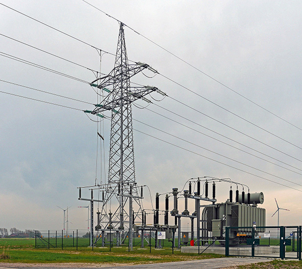
If checking the proper functioning of any part of our electrical system is important, transformer verification is the key part in the electrical powersystem.
Experience in the design, manufacture and repair of transformers has allowed us to know the most important aspects for control and verification, ensuring the correct operation of transformers during their long service life.
The need to verify and prove that the manufactured transformer complies with the characteristics requires the subjecting of a seriesoftests agreed by authorized bodies according to the standard.
Tests for new transformers and their completion procedure are detailed and described in the standard: UNE-EN 60076 corresponding to IEC-76, as the namesuggests.
This article will study the winding resistance measurement of the transformer.
The measurement of the resistance of the windings has three main objectives:
Due to the low resistance of power transformer windings, conventional measurement methods are not in application. Instead, specialized meters generically referred to as "four-wire ohmeters" will beused.
The term "four wires" refersto the number of cables required to measure resistance according to thomson's scheme.
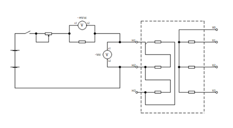
The measurement method used should take into account that the time constant of a vacuum transformer can be several seconds,and specially in high power units. Therefore,the DC takes a while to stabilize and measurements should be made when the current is constant.
Another important aspect is the effect of temperature on resistance. As mentioned above, the resistivity of materials depends to a greater or greater extent on temperature in a ratio called temperature coefficient. The materials used to carry out the windings of the transformers, copper and aluminum fundamentally have a relatively high temperature coefficient which causes the losses by Joule effect in the windings to be, in addition to quadratic with the intensity of the current, direct with the temperature.
Since the interval between which the temperature of the windings varies is small you can use the simplified form of the variation of resistivity with temperature, with which we could write the following expression for resistivity at a certain temperature:
ρθ2 = ρθ1 • [ 1 + α20 • (θ2 - θ1)]
where:
ρθ2 is the resistivity of a certain temperature, in
ρθ1 is the resistivity of the conductive metal, at room temperature, conventionally at 20oC, in Ωmm2/mm
α20 is the coefficient of temperature, or variation of resistivity with temperature, of conductive metal at 20oC with constant mass and free expansion. For annealed copper-type, according to UNE 2003 it is 0.00393 ohms per degree Celsius, and 0.00407 for aluminium, according to UNE 2196.
θ2 It is the temperature at which you want to calculate resistivity, in ºC
θ1 It's the ambient temperature, in ºC
The standards set the reference temperatures at which resistors and all temperature-dependent parameters must be specified. In Spain, for example, the temperature of oil-submerged transformers is 75oC.
At DIGAMEL Substations, we offer a complete range of equipment needed for the measurement of winding resistance.
Contact us by filling out this form:

 ES
ES
 FR
FR
 PT
PT